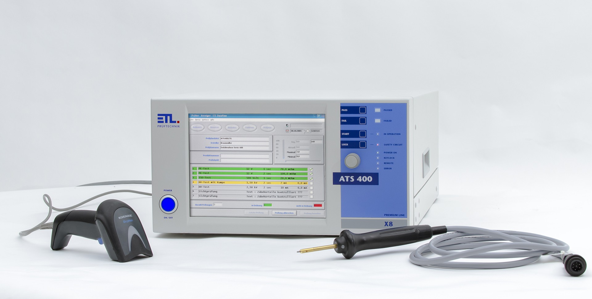
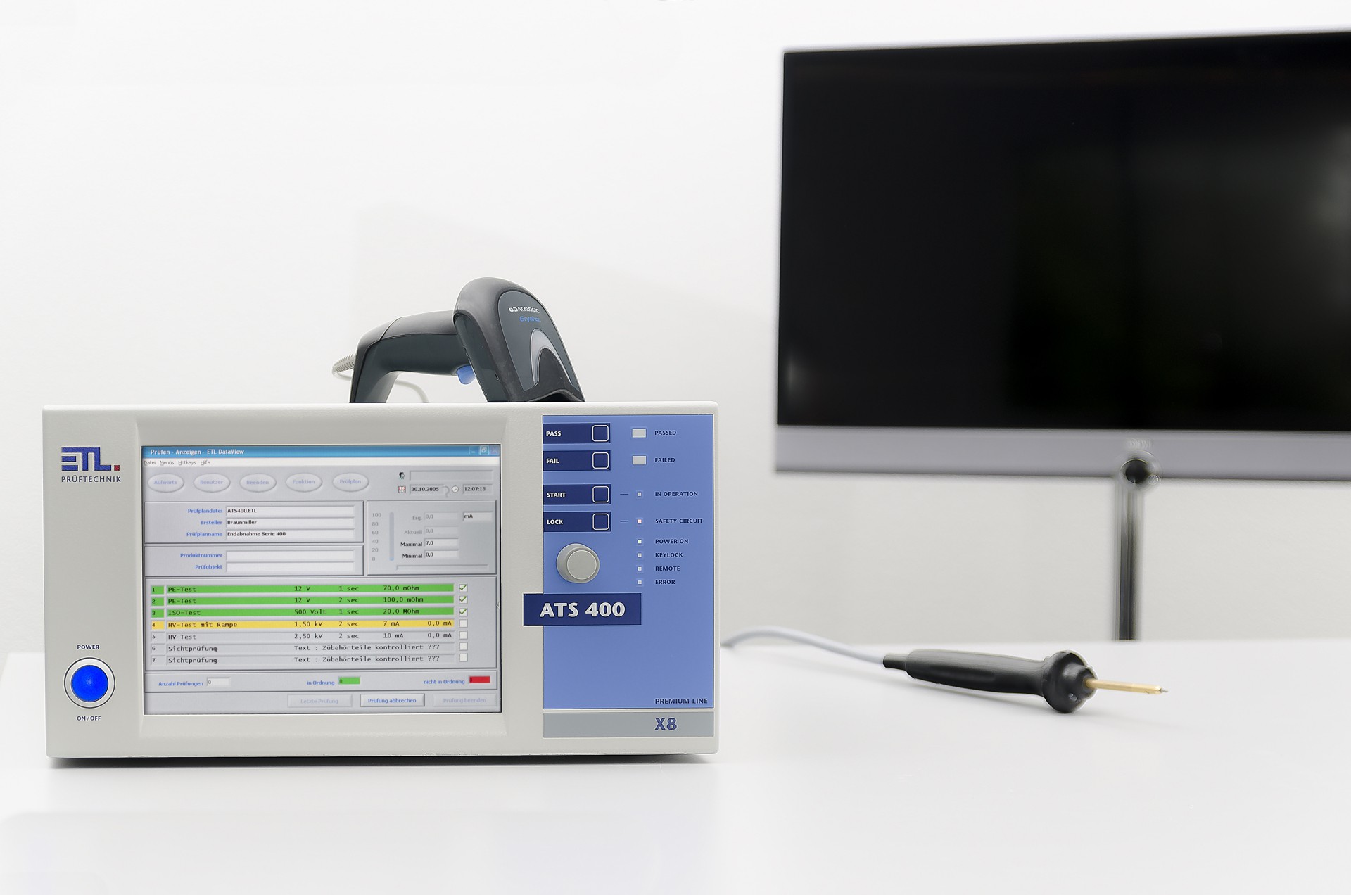
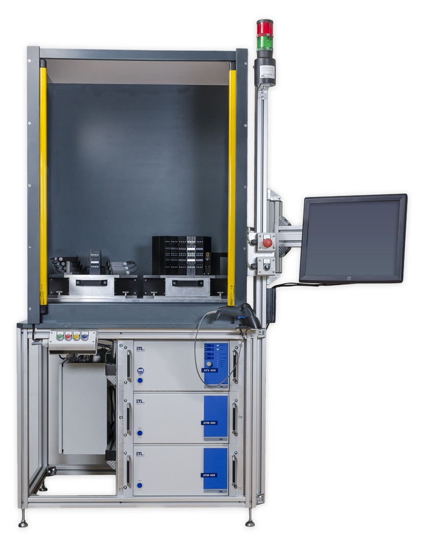
Automatic Test System - Model LG-L
0.5 - 25 A AC, 1 - 500 mΩ @ @
Insulation resistance @ @@ 50 - 1 000 V DC,0.5 - 400 MΩ,@ @ @ @ @ @ @ @ @ @ @ @ @ @ @ @ @ @ @@ current-limited, EN 50191 @ @
Function test, mains @ @ @ 230 V AC, dep. on mains supply@@ @ @ @ @ @ @ @ @ @ @ @ @ @ @ @ @ @ @@ 0.01 - 10,00 A AC @ @
Continuity test @ @ @ @ @ @ @@ 0.5 - 25 V AC, 1 - 600 Ω @ @
General data
| Input voltage | 230 V, 50 Hz / 60 Hz |
| Mains connection | IEC mains cable supplied |
| Tolerance mains voltage | +/- 10 % |
| Current consumption | max. 10 A |
| Fuse | 10 A, T, 5 x 20 mm, 250 V |
| Displays | X2-Variation: no display, remote control variation |
| Operating system user interface | X2-Variation: Only remote control variation X4-Variation: WIN CE ® X5-Variation: WIN CE ® X6-Variation: WINDOWS ® X8-Variation: WINDOWS ® |
| Storage of test plans and results | X2-Variation:Storage through superordinate control unit X4-Variation:Selectable local on SD-CARD, optional USB or LAN X5-Variation:Selectable local on SD-CARD, USB or LAN X6-Variation:Selectable local on hard disk, USB or LAN X8-Variation:Selectable local on hard disk, USB or LAN |
| Setting of test parameters | Manual in the single test menu or via test plan (user interface DataView) all-automatic via interface (ASCII, DLL, LabVIEW, .NET) |
| Error message | Audio, optical and via interface |
| Dimensions (W x H x D) | 400 x 210 x 420 mm |
| Weight | Approx. 23.8 kg |
| Casing | Metallic case, RAL 7035 |
| Basic equipment with delivery | Manual, mains cable, safety circuit plug |
| Calibration | Factory-calibration incl. calibration certificate DAkkS-calibration (BS/EN17025 similar to UKAS) option |
Environmental conditions
| Casing | IP20 |
| Humidity | max. 80 %, not condensing |
| Allowed range of temperature | + 5 to + 40 °C |
| Max. hight above sea level | 2 000 m |
| Cooling | Internal fan cooling |
Interfaces
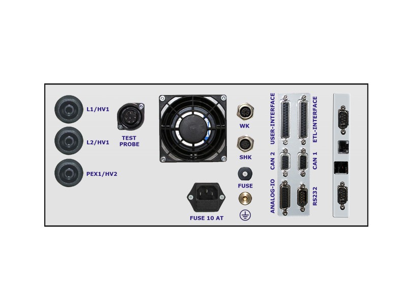
| ETL-Interface / Digital-IO | Start, stop, good result, bad result and test in progress (all digital outputs are solid state) |
| RS232 / PC- Interface | Remote control interface for customer applications or for data management package ETL DataView |
CAN Interface | For expanding the test system by additional devices and additional ext. extension test modules |
| LAN Interface | For connection to the customer's own network, e.g. for storage of the test results, depending on the operating variation |
| USB port | For connection to external storage device as well as keyboard and mouse, depending on the operating variation |
| VGA-port | For connection to an external display, only X6- and X8- models |
Connections – test object, safety components
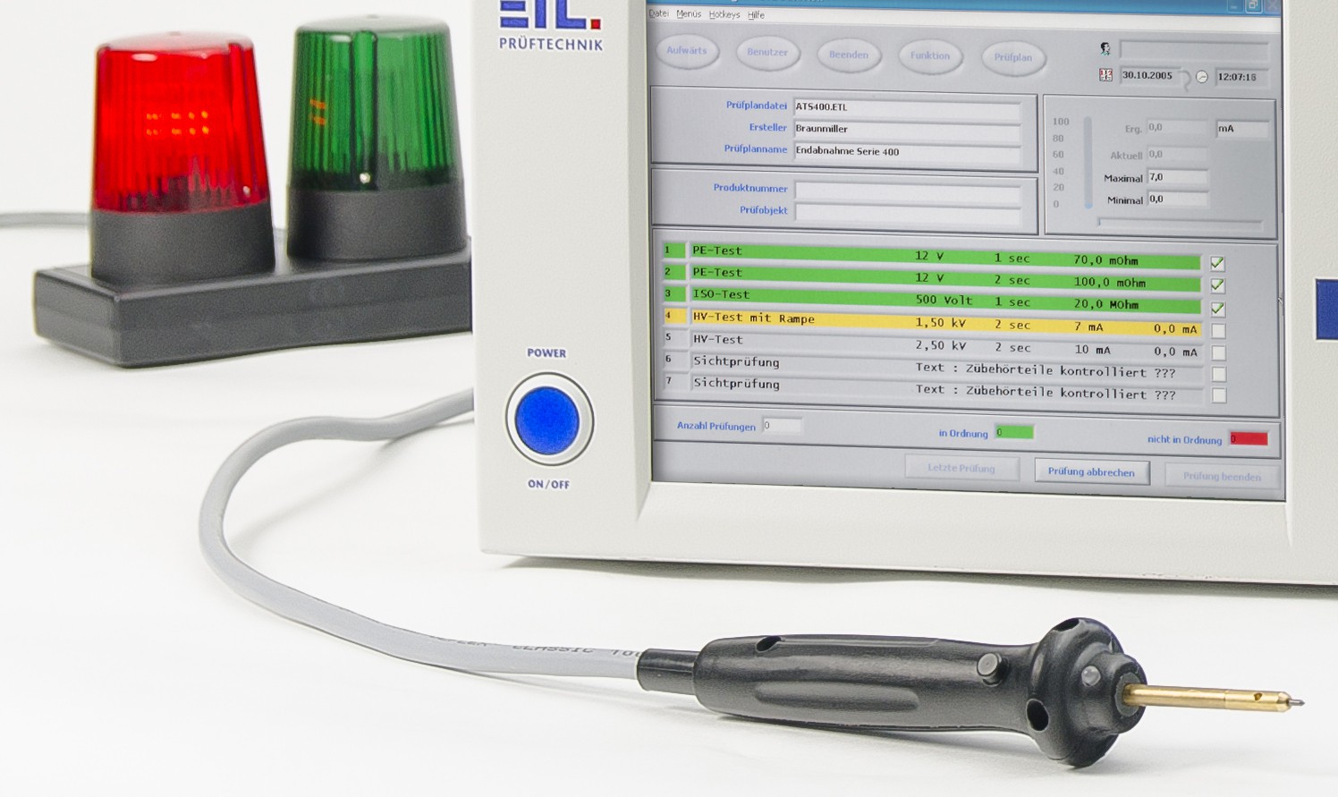
| Signal lights | For connecting a combined green/red warning light according to EN 50191 |
| Safety circuit | Three different options of safety circuit available |
| Connections for the test object | L1/HV1: connection phase DUT * |
| Mains connection | IEC connector, 10 A, with fuse |
| USER-Interface / Digital-IO, optional | Digital interface for full remote control (all digital outputs are solid state) |
| Analogue-IO, optional | 4 analogue input signals (0 - 10 V DC) 2 analogue outputs (D/A), for example: results monitoring |
| Frequency-IO, optional | 4 frequency inputs for recording speed- and there rotation-direction |
Expanded device-Setup
| User administration | Individual setup password protected |
| Signal configuration | Individual setup for digital results |
| Data manager for test plans and results | Individual setup of storage options, storage location, naming of the result files and automatic creation of sub-directories |
| Buzzer-options | Individual setup of acoustic warning |
| Basic settings of the test system | Language selection, device name, interface configuration |
| Start of the operating interfaces | Individual setting of the start menu. (e.g. direct start in the test selection menu via barcode) |
| Test selection menu | Manual via selection window, process reliability via barcode- or keyboard entry, via digital interface or through read-out of a files |
| Manager for dummy testing | Dummy testing can be set according to the configuration: automatically requested (e.g. at program start, at user changes, via digital interface, after a certain number of test objects, a certain time or after a time interval) |
| Locking options for the test cage | Individual setting of the locking options (during the test, on Good, on Bad, …) Optional module |
Start options for testing
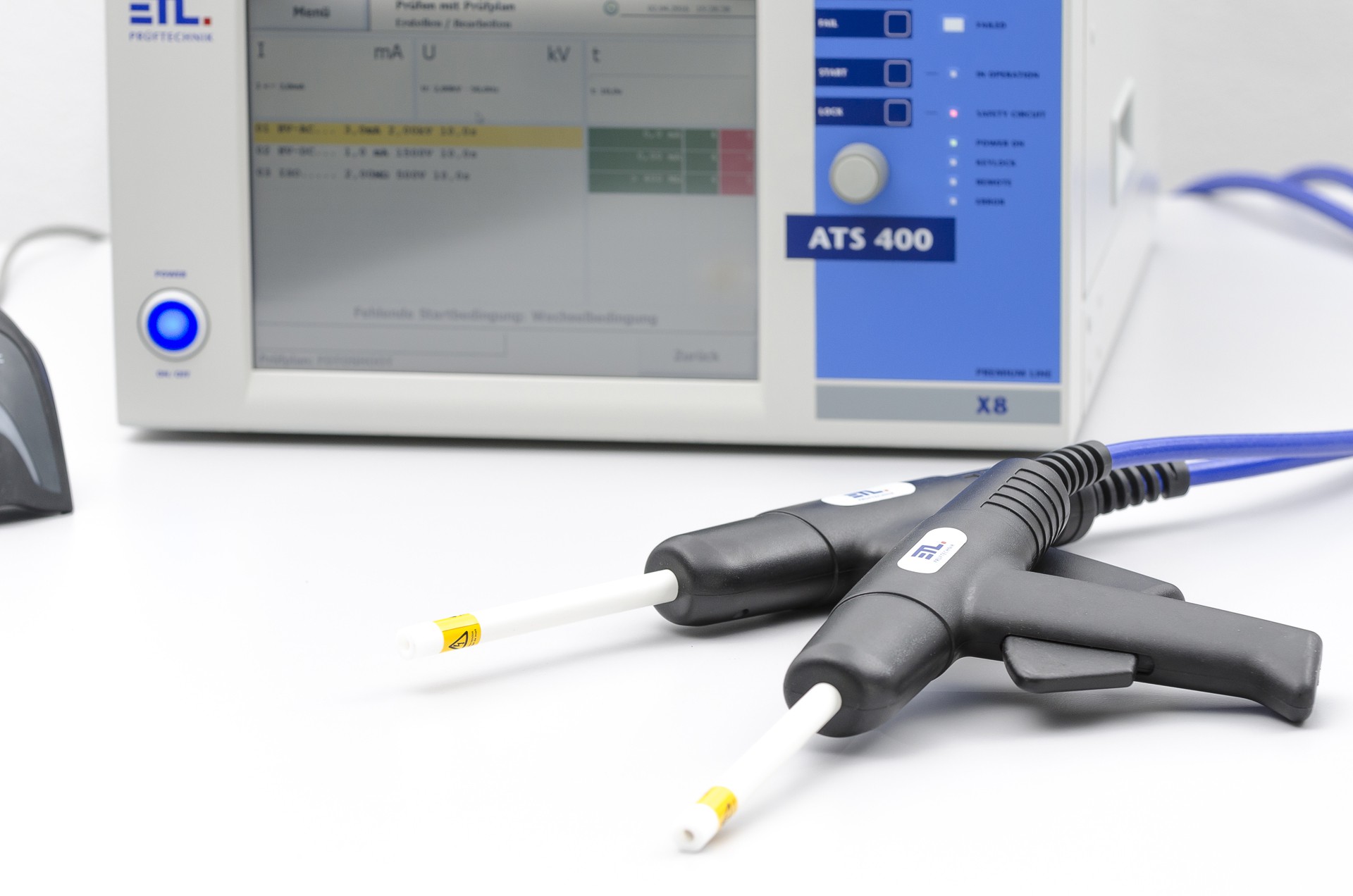
| Start- and stop- signal by test pistol * | Special 4-wire-technology for automated test start and connection monitoring. Test voltage will only start when both test pistols have contact to the test object. (depending on the built-in test modules) |
| Automatic start via safety circuit | The test can be started when the cage door is closed, for example. |
| Start button on the device | Front panel button for test-start |
| Start via contact monitoring, patented* | Start will only take place if the source and sense are connected, without cable break |
| Start by serial interface | Start takes place through higher-level control system (SPS or PC) |
| Start by digital interface | Digital I/O for example as PLC, footswitch, push button, etc. … |
| Start options | individual setup of start modes |
(*) patented:
The ETL contact monitoring (KÜ) is a patented technology:
German patents: 100 11 466.0 and 100 11 345.1
European patents: 01 105 568.8 und 01 105 567.0
Electrical safety and norms
| EN 61010-1 | safety regulations for electrical measurement, control- and lab- equipment |
| EN 61326-1 | electrical measurement, control- and lab- equipment – EMC-requirements |
| EN 61000-3-3 / EN 61000-3-2 | Electromagnetic compatibility (EMC) |
| EN 50191 | Erection and operation of electrical test equipment |
| EN 60598-1 | luminaire / Part 1: General requirements and tests |
| Contamination level | 2 |
| Protection class | 1 |

